|
|
Virtual PhotonPower ConverterQuantum Converter patent pending |
|
|
Virtual PhotonPower ConverterQuantum Converter patent pending |
|
(for a brief pdf version [2p] click here) This is an exercise involving customizing
the electromagnetic fields exhibited by a coil with separate dedicated
phased energy sources. One energy source produces the magnetic field
component -- current, while the other produces the electric field component
-- voltage. These two energy sources excite, through induction, a
closed conductive system such that the induced fields/currents in the closed
conductive system causes a coil in the system exhibit an electromagnetic
field with intrinsic properties.
|
|
Physics, in the field of quantum electrodynamics,
hypothesizes the existence of virtual photons. These are hypothetical
photons with an infinite amount of potential energy. This virtual
photon explanation is used to explain the amount of physical force that
can occur for a relatively small amount of electrical work with Coulombs
Law and some gravity issues.
Here is (hopefully) a clear electrical perspective VPPC operation. This explanation takes the VPPC theory out of the esoteric virtual photon range into a common recognized electrical theory. For any single phase power transformer attached to the grid the primary winding has an electro-magnetic footprint. Part of this footprint is that the primary is in an electric field. Out of this electric field across the primary there is an electron flow through the primary winding creating a magnetic field. Energy from the grid that creates these electric and magnetic fields is translated through the fields by the secondary winding and then to the house or whatever. The secondary gets its energy from these fields. Both the electric and magnetic fields
fluctuate with the frequency of the grid. The electric field component
stays the same according to frequency and for the most part is constant.
However, the magnetic field electron flow varies with power draw and
is what translates the energy transfer. The current flow
magnetic field -- in the primary is directly proportional to the energy
VA -- being extracted from the transformer.
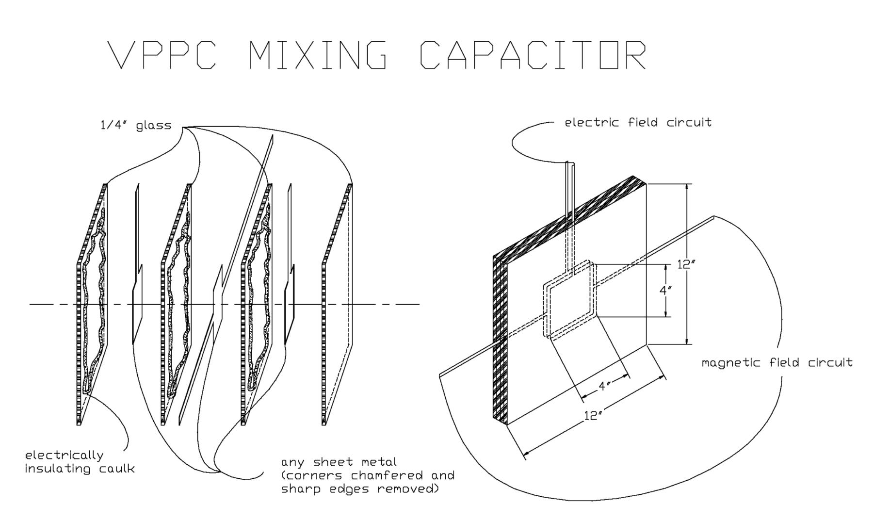
With the VPPC there are two energy
sources. The electric field energy source suspends the primary winding
(7) in a closed circuit electric field. With the electric
field circuit, being a capacitive circuit, there is little to no current
going through the primary (7) as it is polarized and suspended in
the electric field.
The major VA consumption with this device would be the current source generating the magnetic fields in the electric field suspended primary winding. In addition this power consumption would be inversely proportional to the electric field potential voltage across the coil. For any transformer and a given power draw, the higher the voltage field across the primary, the less the current in the magnetic field circuit. In summary, this device would give a
single phase line transformer the electro-magnetic field footprint and
VA
capabilities of when it's attached to the grid with a VA input that is
a fraction of its VA output. Energy is pulled out of the virtual
photon quantum state to do this.
|
|||||||||||||||||||||||||||||||||||||||||||||||
| Schematic
and Drawing Numeric References
|
|||||||||||||||||||||||||||||||||||||||||||||||
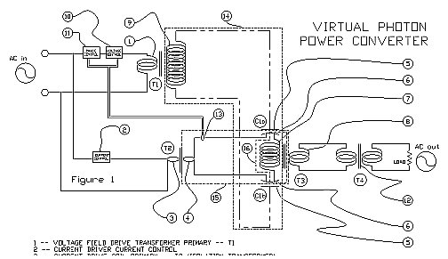
| Explanation
of Drawings
Magnetic Field
Circuit -- 15
Electric Field
Circuit -- 14
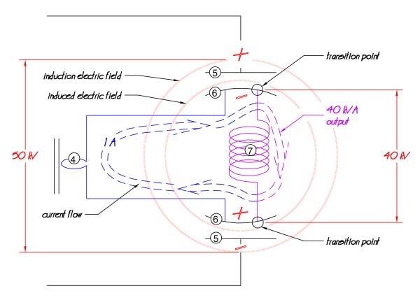
The high voltage secondary (9)
is connected to a set of high voltage capacitor induction plates (5
-- C1a+b). For very high voltage applications, T1 would
be a Tesla wound coil. Let us say, for the sake of argument, that
this high voltage is 50 kV [50,000
volts]
Each opposite plate of the high voltage
capacitor plate mixing capacitor voltage/current mixing plate -- C1a
& b (6) is connected to the opposite ends of a coil (mixing
transformer T3 primary 7). Said primary is positioned
between (6) such that the induced high voltage across the capacitor
demonstrates as a high voltage across the mixing transformer primary (T3
-- 7) [assuming there are
losses this is shown as 40 kV] .
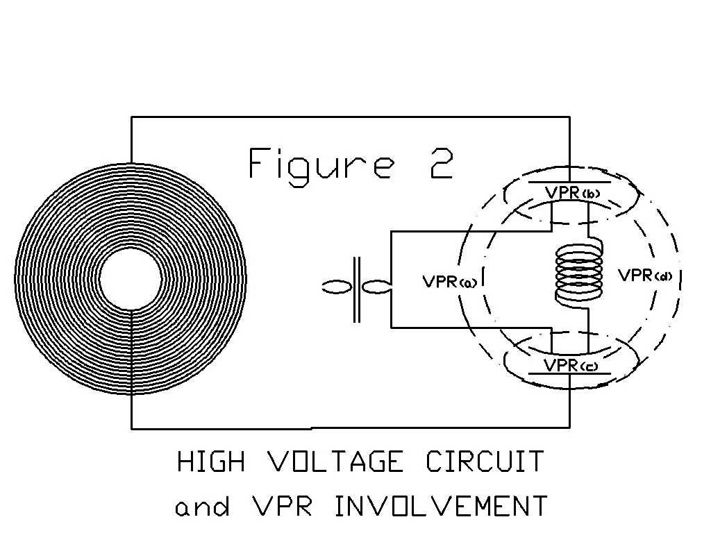
Therefore, what the voltage circuit (Figure 2) is; is a transformer attached to two capacitors connected in series with some kind of active impedance device in series between the two capacitors. Typically, this type of circuit would draw very little current and be a low VA. (depending on capacitor size or voltages used) This active impedance (see high voltage circuit diagram) involves (depending on phase relationship) the secondary of the current drive transformer (T2 -- 4); which would actively facilitate the current transfer from C1a 6 to C1b 6. The current from the magnetically driven circuit can power drive (if you will) the migrating charge between C1a 6 to C1b 6 of the voltage circuit. In addition, this active impedance may also involve the expanding and contracting magnetic fields of the mixing transformer primary (T3 7). The current of the electric field circuit
would be (total voltage)x(total capacitance)x(120).
|
|||||||||||||||||||||||||||||||||||||||||||||||
| Electric
Theory Operation (for
a pdf handout version of electrical theory click here)
In more electrical detail, assume:
As T2 is producing a 1 ampere current flow, the voltage across T3 primary (7) will be the usual out of phase voltage/current relationship of a coil. This is where the electric field circuit -- 14 -- comes in. Another voltage is injected at this point across T3 7 -- mix point 16 . The voltage of the electric field circuit (T1) can be much higher than the original input voltage produced by the current drive transformer (T2). As the current in the magnetic field circuit enters the capacitor mixing plate (6) to the primary of the mixing transformer (T3 7), that current is now in a much stronger electric field than it originally was in. The primary -- mix point 16 -- (T3 - 7) sees it is being energized by a higher voltage. Let us say now that T3 7 has 40,000 volts across it from C1a and C1b. The mixing coil secondary (T3 8) is going to be excited by a coil that has 40,000 volts (or whatever) across it with the magnetic field current of 1 ampere. In other words, the secondary would have a 40,000 VA capabilities. This is a device now that has 50+ VA going in (the + being the low VA of the high voltage circuit); while, it is producing 40,000 VA at its output. It is recognized that this is an apparent violation of the conservation of energy. Please see Physics Theory Operation for an explanation. This unit can also be cascaded; meaning, the magnetic field circuits are connected in series while the electric field circuit is connected in parallel to the series connected magnetic field circuits
|
|||||||||||||||||||||||||||||||||||||||||||||||
| Physics
Theory Operation
Again, as with the Electric Theory Operation, numerous assumptions must be made: Assuming: The current physics theory of infinite potential energy of virtual photons is relatively accurateAdd on to this: Assuming: Electric fields can is able to have a Virtual Photon Reference (VPR)
The goal behind this is to put electrical energy into a VPR system, tap into the infinite potential energy of a VPR, and bring some of this infinite potential energy into actuality with it as it comes out of the VPR system as electrical energy a power amplifier. This system is trying to do this by feeding the input power into a closed high voltage capacitance system. Going on the assumption that the stronger the electric fields the more the VPR involvement, as evidenced in Coulombs Law, then the higher the voltage across C1a 5 to C1b 5 the more power this device should have. With the idea of expanding and contracting magnetics fields of the coils between the VPRs, and with T3 7 especially, adds what may be another set of considerations to the electrical schematic. Specifically, can the changing electric fields of the capacitors be linked to the changing magnetic field of T3 7 ==> T2 4 circuit such that together they form their own intrinsic photon? This may involve playing with the magnetic field shape, polarity, and configuration. In addition, this also may involve the spatial relationships between the capacitor plate-coil-capacitor plate combination along with a spatial relationship to frequency. Perhaps, for future study.
1, Both 10 and 11 can be any off-the-shelf devices available and may vary from a simple rheostat and a LC or RC network (in which case 13 would not be necessary), to a dedicated slave AC power supply (as mentioned in the Summary) with a variable phase lock using 13. |
| Home | About | Contents | |
| Purpose | Downloads | Order | Exercises |
| Virtual Photon | Electric Field Transformer |