|
This web page is about playing with numerous ways the three right angle
vectors of an electro-magnetic event can be arranged that produce a custom
electro-magnetic envelope that has intrinsic characteristics.
There are a lot of What ifs? on this
web page. The author recognizes his ignorance. As the movie
goes, I know two things Jack and sh*t; and Jack left town. The
intention of this web page is to examine the basics of an electromagnetic
event and pique other people's curiosity and have them go Hmmm, that's
a good question. Let's find out.
Many of the questions presented here could not be answered by the authors
college instructors and may not be answerable without direct experimentation.
There are probably a few people (several thousand, actually) that have
answers to some of the questions posed here; the answers to a few of these
questions may be obvious to them.
One of my college instructors was responsible for the electronics of a
high power AM radio station when he was younger. He was quite knowledgeable
in EM field theory, tuned circuits, high voltage-high frequency, etc.
He also gave us a proper introduction to the history and evolution of electricity
and, of course, Tesla. (Thank you Mr. Mulky)
Another thing that was learned from electronics and world history concurrently
was how mankind would develop a concept and then crystallizes in that concept.
Some examples are Greek pottery, TV, and AC distribution. With Greek
pottery, they developed 5 different pots for a multitude of purposes.
Once these pots were established, no other types of pots were made.
They crystallized in their thinking.
With TV and AC distribution, both were first developed in the US.
The US developed a system that delivers 117 volts at 60 Hz and kept it
there. Europe developed their system later with ~220 volts at 50
Hz which tended to be able to deliver more energy. A similar thing occurred
with TV.
Again, the primary intention of this web page is to awaken people's curiosity.
What happens if we do this? The idea is to get people to re-examine
some crystallized thought.
|
|
ELECTRO-MAGNETIC
FIELD (EMF) BASICS
An electro-magnetic event involves three right angle vectors, a changing
electric field, a changing magnetic field, and a change of space at light
speed -- c. These three right angle vectors define 3-dimensional
solid matter as we experience it.
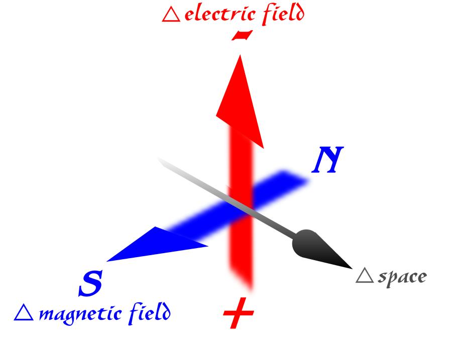 |
A creation of one vector automatically creates the other two; a changing
electric field creates a changing magnetic field with a change of space,
while a changing magnetic field creates a changing electric field and change
of space, and a change of space (close to c) creates a changing
electric field and a changing magnetic field. |
Be advised, our knowledge of EMF is based on its reaction to matter.
All matter that we experience is comprised of an electric field matrix
of electrically charged particles. This electric field matrix manifests
in non-organic -- non living -- matter as crystalline in nature as an ordered
array. While, organic living -- matter is comprised of electric
field matrices within matrices, within matrices
One element of a crystallized atomic/molecular matrices have particles
or collection of electrically charged -- positive -- particles that are
relatively stable in space do not move much, are the atomic nuclei, and
act as place holders within a crystallized electric field matrix.
Their relatively constant spatial relationship is an integral part of a
crystalline lattice. While, the negative electrically charged
particles electrons -- are in a constant change of relatively large distances
of space and move between the place holders.
The electric field matrices developed by these electrically charged particles
determine the apparent qualities of the material -- characteristics, some
of these qualities are intrinsic to that matrix. An example is carbon.
A carbon electric field matrix can have the characteristics of soot, activated
charcoal, or that of a diamond; the matrix the material is in defines the
apparent characteristics of material.
Some of the characteristics of relatively simple crystalline matrix are:
1.) If
the electric field matrix field strengths are so strong that the moving
electrons are locked into the matrix and do not respond to an outside electric
field and are not allowed to leave their place around their respective
nuclei, that material is considered an insulator.
2.) If
the electric field matrix field strengths are loose enough that they can
respond to an outside electric field, yet the electrons not leave the immediate
nucleus, and the matrix can transmit the field through electric induction
atoms/molecules become electrically polarized, that material is considered
a dielectric.
3.) If
the electric field matrix field strengths are loose enough that electrons
are allowed to leave the immediate nucleus vicinity, the material is considered
a conductor.
4.) If
the electric field matrix field strengths are tight under one set of conditions
(1) and loose under another set of conditions
(3), that material exhibits semi-conductor
properties.
5.) If
the electric field matrix allows for circular movement patterns of the
electrons, the material exhibits magnetic
qualities
As to the qualities of each EMF vector, each vector component is somewhat
different. Here is a comparison list of some of their known qualities.
Electric field
-
Stores energy
-
Measured in voltage
-
Can vary in field strength -- density
-
Can be stopped by an atomic/molecular electric
field matrix -- can be insulated against
-
Physical strength
-
the inverse square law is involved
-
an infinite energy potential is available
-
Polar in quality
-
A change of electric field uses two points
references
-
Referenced from positive to negative
-
Opposite poles attract, similar poles repel
-
The change of an electric field is considered
between these two references, either in distance or in strength
-
If either reference changes like in charge
strength or distance the field density changes
Magnetic field
-
Stores energy
-
Measured in gauss
-
Can vary in strength -- density
-
Can not be stopped by an atomic/molecular
electric field matrix can not be insulated against
-
Some amount can be absorbed by the complex
organic living -- electric field matrices, kind of like a sponge.
-
Physical strength
-
Does not work with the inverse square
law
-
Much weaker than the electric field
-
Polar in quality
-
Referenced from north to a south
-
Opposite poles attract, similar poles repel
-
A change of magnetic field uses these two
references
-
Distance between poles changes field density
-
The change of an magnetic field is considered
between these two references, either a change of distance -- spatial reference
-- or in strength
-
If either reference changes like in flux
strength or distance the field density changes
Change of space
-
With movement of mass, it stores energy
-
Strength
-
When generated by either a changing
electric or magnetic fields, it can not be stopped
-
Is a constant c
-
Polar in quality
-
The polar qualities are in time and
space
-
A change of space occurs in a change
of time and vice versa
-
Both of these time and space values
are dependent on frequency and are relatively constant for a given frequency
Create any two of the EMF vectors and the
third vector created is more powerful:
-
Create a changing electric and magnetic
vector
-
and the change of space, with minor
exceptions, never changes c.
-
Create a changing magnetic field
and a change of space
-
If the change of space of is a conductor
matrix moving within that magnetic field we have power generation.
-
If the changing space is the expanding
and collapsing of magnetic field and it is the field that is moving through
a conductor, this is magnetic induction -- transformers.
-
Change of electric and a change of
space
-
Depending on the type of motion, the
material has magnetic qualities, See (5) above
Admittedly, this is an over simplification of an electro-magnetic event.
All our electrical doodads are based on applications of -- playing with
these three vectors.
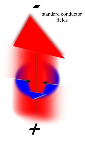
With most conductive devices, the initial EMF generated by that device
has a spatial polarization such the movement vector is toward the device;
the electromagnetic field created by the electric field in the wire and
the magnetic field created by the electron movement has change of space
polarized to move inward.
The like same field direction -- polarized fields that are constantly
being created push the previously created fields away from the device;
it pushes energy away from the device in the opposite direction
of the spatial vector created by the fields towards the device.
When the initial electric field pressure/voltage -- begins to weaken,
then the motion vector causes the EM field to collapse in on the device;
the stored energy is put back into the system.
For the most part, the electric field and the magnetic field are in phase
occur at the same time. The magnetic field can lag in phase behind
the electric field some, depending on the self induction of the device. |
 |
It is interesting to note that for any AC power distribution grid, energy
available in one part of a system is usable in another part of the system
through electric and magnetic fields. Any AC power distribution system
is an electrically neutral grid or matrix of conductors.
This matrix is then suspended in an electric field, subject to a voltage.
The electric field more or less defines the potential energy the matrix
or grid is capable of moving; it is the energy's window. It is
through the magnetic fields created within these energy windows transformers
-- that translate the energy into a usable form, a light bulb.
It is as if when AC electric and magnetic fields act as a conduit for
energy, the electric fields is similar to the cross-sectional area of the
conduit, while the volume of energy is translated through the conduit
with the magnetic fields created within the electric fields.
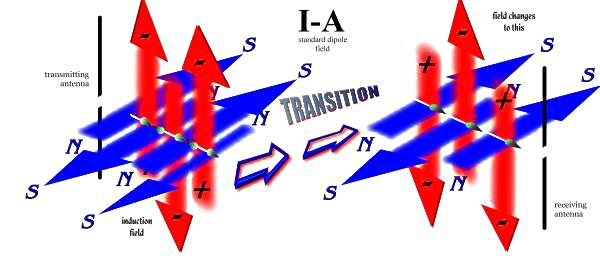
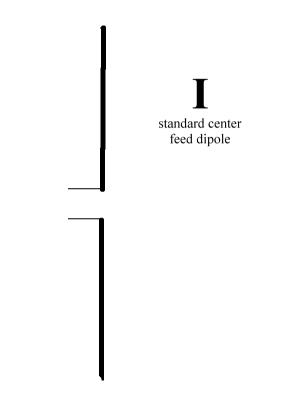
With EMF producing devices like dipole antennas (I),
the initial fields created are different. The first quarter wavelength
has the motion vector -- change of space -- away from the device.
The second quarter wavelength, as voltage decreases produces a motion vector
that collapses towards the device, the third quarter wavelength
away
from the device, and the forth towards, etc. (I-A)
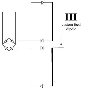
| DIPOLE FEED
CONFIGURATION SCHEMATICS |
 |
 |
 |
 |
Some radio wave characteristics are:
-
A typical dipole antenna's (I)
initial field structure has the electric and magnetic field elements being
radiated 90o out of phase (I-A).
A changing magnetic field is initial and weakens as the electric field
strengthens until it is nonexistent when the electric field is at max,
-
The initial right angle change of space
vector is away from the antenna. Then, as the current flow changes,
the magnetic field goes in the opposite direction and is the strongest
as the electric field becomes non-existent as it reverses polarity.
The right angle change of space vector is now goes towards the antenna
(I-A).
As the reverse polarized electric field gains strength, the magnetic field
weakens, etc.
-
This 90o out phase production
is the antenna's induction field with alternating direction vectors.
Outside of the induction field (about one or two wavelengths), the electric
field and the magnetic field make a transition and become in phase with
a continual change of space away from the antenna (I-A).
Let's call this transition point 1.
Some of the questions below are asked in referenced to a dipole antenna
(or similar device) hooked up in in a number of ways in order to produce
specific electric and magnetic fields (as shown in the schematics) .
It is recognized that with some of the more advanced ideas (III
or IV),
the schematics may stay the same but the devices may evolve to be something
other than a simple dipole. The dipoles in those drawings are there
to represent devices that produce the fields illustrated. |
|
WHAT
IF QUESTIONS
Here begins the game of What ifs?
Given the "playing field", what if we
do this? One major
what if I
remember asking in college is:
-
What if
an EM field is created that is continually pushed in the opposite direction
of its motion vector?
The answer I remember receiving is that the EM field will flip polarity
and radiate outward. This answer, if correct, in itself warrants
further study. (if it hasnt been already) Because:
-
This means either the magnetic field or
the electric field changed polarity
-
Which field changed and why or when?
-
How strong is this change; meaning, can
it be prevented from occurring?
-
If this change of polarity transition occurs
in the immediate area of the device, what are its spatial dimensions, in
wavelength, or in distance from the device?
-
Let us call this transition
point 2
-
Is there a relationship between transition
point 1 and 2?
As to some of the above schematics, here are more what
if questions:
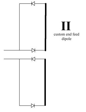
-
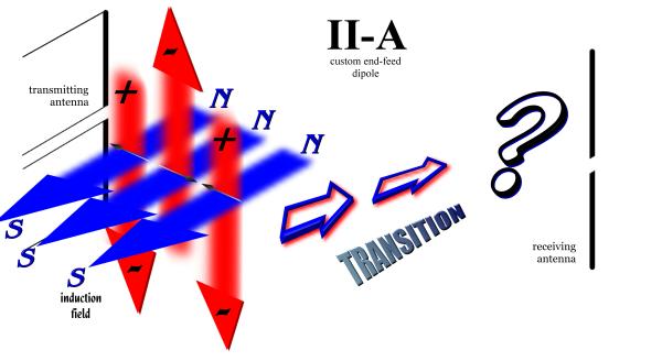
What if:
A diode array is used to control either end of an antenna element as a
feed point as in (II).
The ways the diodes in (II)
are placed are such that the initial field produced has the initial motion
vector towards the antenna.
-
What happens to the wave form when the
initial wave is collapsing back on itself (as opposed to normally radiating
outward)? This would occur if a normal dipole (I)
is an end feed instead of a center feed as shown.
-
What effect, if any, does the 90o
phase shift of the initial motion vectors have?
-
What if:
An induction field is created where the magnetic field polarity doesn't
change while the electric field changes polarity? (as in II-A)
-
What effect, if any, does having the motion
vector change every ½ wavelength instead of every ¼ wavelength
as in I-A.
II-A
shows the respective electric and magnetic fields as being in phase.
-
What if:
the respective fields were 90o out of phase?
-
Conversely, what
if an induction field is created where the electric field polarity
does not change polarity (using a full wave rectifier bridge on a dipole)
as the magnetic field changes?
-
What happens to these fields once they
make their transition after transition point
1 -- and what are the resultant vectors electric/magnetic/space
produced?
With both of I
and II
examples, the change of space vector is alternating between being away
and towards the antenna.
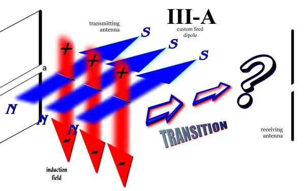
Schematic III
introduces a full wave rectifier bridge before Schematic II
thereby maintaining a constant electric field polarity as well as a constant
magnetic field polarity. This introduces more What
ifs:
-
What if:
the electric field and the magnetic field do not change polarity thereby
creating a change of space in a continual direction.
-
One resultant could be a pulsing DC moving
away from the antenna as in III-A.
-
With the fields polarized so that the other
result would be creating a pulsing DC continually collapsing in on the
antenna with field structure similar to a normal conductor.
With schematics I,
II,
and III
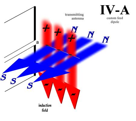
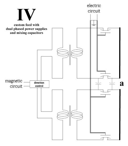
the exciting energy is coming from a single energy source. Now, what
if the fields are customized further using the mixing capacitors
flux capacitors :) -- and dual phased power supplies of the quantum
converter as in IV?
Thereby, giving independent control to each field component. (Schematic
IV
allows independent control strength or polarity -- of both electric and
magnetic vectors and shows only one of a multitude of hookup variations
possible.) .
-
What if:
Using a schematic similar to IV,
the electric field and magnetic field of III-A
are
90o out of phase, as in IV-A,
with a wave being constantly pushed out in the opposite direction it is
polarized to move in. Because of the out of phase relationship of
the electric and magnetic fields, will an envelope be created that is constantly
being pushed in the opposite direction of the motion vector
-
What kind of polarity and phase transition
transition points 1 or 2,
if any, do the fields make away from the induction field with the last
example?
A reminder is that electric and magnetic fields store energy. Expanding
fields carry energy in them; and, with normal conductors, the collapsing
fields put energy back into the conductor which takes the energy away.
This brings up an interesting question.
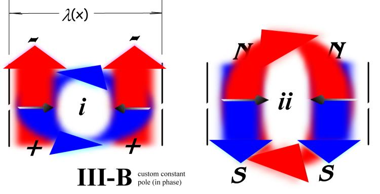
-
What if:
a circular EMF is collapsing on itself and there is nothing there to take
the energy away? Say that a in III-B
or IV-B
is large enough that the collapsing constantly polarized fields are not
converging on any device. This would mean that the energy carrying
EMF is collapsing to a theoretical point without any device there taking
the energy away.
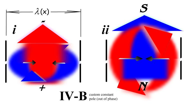
-
With the cases of IV-A
and B,
and considering each successive field is carrying energy, and there is
nothing there to take the energy away, would there be a theoretical center
point a -- where the energy of successive collapsing waves is
stored in stronger and stronger fields such that the energy stored in the
fields can approach the summation of all energy expended up to that moment
in time?
-
Or
because the energy has nowhere to go,
will the collapsing energy change and manifest a constant polarity EM envelope
with the space vector moving outward, creating a one point EMF source
creating a transition point 2?
STANDING
WAVES and WAVE SHAPING
Some of the previous examples are shown where the antenna elements are
at the center of an electro-magnetic envelope it is creating. In
addition, some what if questions relate
to the effects the fields have when the envelope created is created with
a multiple set of devices; the devices are not at the center of the envelope
created.
-
Now, as with the
last question, what if: the
elements where outside of the event they were creating at some function
of wavelength away from the center of the event, a quarter wavelength for
example. In III-B
or IV-B
something like cage matrix of antenna elements is shown that is creating
the event at the center with a sort of standing wave created within the
cage.
-
What if:
there is a number of antenna arrayed in a circle, wired, and fed such that
the center of the induction envelope produced (electric, magnetic, or both)
has a constant field polarity -- IV-B.
Here are more what ifs related to this:
-
Not changing field polarities, they are
in phase, and the change of space is continually towards the center --III-Bi
or ii.
-
Feeding the cage elements such that they
are out of phase while collapsing IV-B
i or ii.
Again, what form does the energy take when it reaches the center?
-
Feeding the cage elements such that they
are out of phase giving the center moving fields a rotation.
-
Any of the above with the change of space
of the fields created by a phase rotation within the antenna matrix itself.
Thereby, creating something like a rotating single polarity electro-magnetic
envelope. With each half wave produced by the antenna elements reinforcing
the fields already produced.
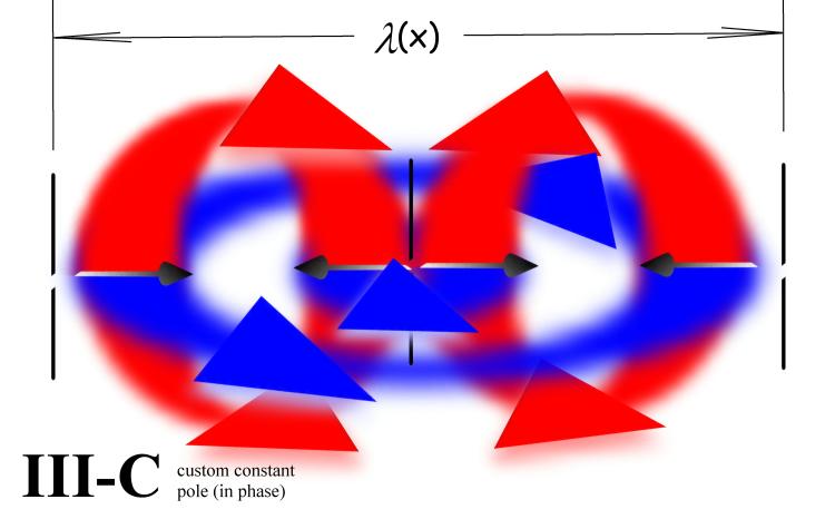
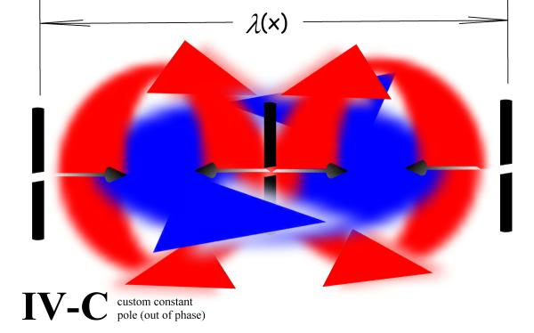
Now lets kick it up a notch. What if:
the resultant induction EMF is a torus or doughnut shaped? Perhaps,
creating EM structures like III-C
or IV-C.
Again, with an EM field constantly collapsing on itself, what effect, if
any, does transition point 2 have?
At the same time, another set of what if questions
can arise with a reflected wave or induced wave from a nearby outside object
is involved. Specifically, how something like an object or the ground
would react to the produced induction field. Such as:
-
Whether the returning wave is a reflected
wave or an induced wave. (An induced wave is where an object responds
to an incoming EM field and produces a field of its own; usually this occurs
with conductors.)
-
What if:
At some function of wavelength (1/4, 1, or ½, etc.), the emitting
EMF has the identical vectors as the reflected EMF. Conceivably,
could repulsion or attraction be induced?
-
The above question can be asked with the
returning wave form matching the induction field
-
This may be more noticeable if one of the
fields is torroidal meaning, field poles emergent from the center
-
Or it can be asked if the returning wave
form is after the induction field has made its transition
1 or 2.
-
Or what happens when the transition
points 1 or 2 are included
into the event
-
What effect will the ground have on the
envelope being radiated? (See directive diagrams in The A.R.R.L.
American Radio Relay League Antenna Book for examples of field nodules
being created by an induction field.)
If all this is not enough, here are some more what
ifs:
-
What if a self collapsing or rotating electro-magnetic
toruses torii uses a function of wave length that is created?
-
Incorporate transition
2 and produce something as in http://en.wikipedia.org/wiki/File:Inside-out_torus_(animated,_small).gif.
Or http://en.wikipedia.org/wiki/File:Clifford-torus.gif.
-
Combining the reflected standing wave concept
with a shaped wave form introduces more what ifs.
To understand how wide open this "playing field" may be, this page hasn't
addressed the concept of a moving mass storing energy. The amount
of energy stored is directly related to the amount of mass and/or velocity.
What
if the energy contained in collapsing electric and magnetic
fields becomes translated into the motion vector. Specifically, the
energy becomes translated into the motion vector of a moving mass.
Would that mean the mass and/or velocity must change? |